Milling operations from geometry to unit price
A reliable calculation for CNC milling parts begins with the question of which surfaces and characteristics have to be processed and from which stock the component is produced. CNC Kalkulator combines CAD geometry, material, tolerances and surface requirements with the master data of the production operation. For the released part area, this results in an editable processing sequence, which technically confirms work preparation or calculation before use.
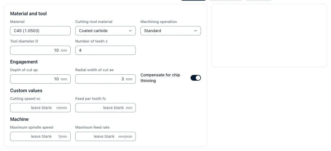
Planing, roughing, residual roughing, finishing, drilling, threading and deburring can be evaluated separately. In addition to material removal, tooling, delivery, feed, speed and machine performance influence the main time. Positioning, rapid response, tool change, probing and other machine functions are considered as non-cutting times. Additional stresses, long tool elongations, residual areas or increased testing effort remain visible instead of disappearing in a flat-rate supplement.
This gives CNC pay-makers a comprehensible basis for manufacturing costs and offer variations. Different batch sizes redistribute set-up and one-off costs each time. A machine change can be counted as a separate variant, so that technical and economic effects remain comparable. Manual adjustments are stored on the basis of justification.
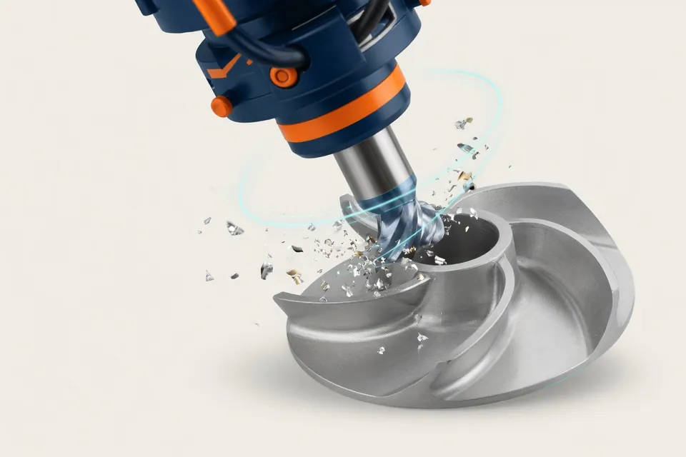
CNC Kalkulator creates a transparent precalculation for the tested parts, machine and process area. Complex free-form surfaces, residual material states, special tools and simultaneous 5-axis machining are evaluated with the concrete operational process. CAM programming and collision check then provide the detailed tool paths; skilled personnel confirm clamping agents, accessibility and productive feasibility.
The complete calculation path with time portions, clampings and relay shows Calculation Milling parts. In Pro, the app automatically creates this calculation path from drawing and STEP model as a calculation draft, which you check and release; for more information see Full automatic calculation from drawing and CAD.
Trackable milling times
Any significant amount of time remains visible and can be specifically checked.
Evaluate characteristics
Geometry, material, tolerances and surfaces lead to verifiable processing steps.
Consider tensioning
Stretching, touching and difficult-to-access areas remain visible as effort.
Maintain CAM boundaries
Freeform and 5-axis cases are calculated only to the extent that they are actually validated.