Machining time from main time, tool change, side time and set-up part
The CNC machining time is calculated from the times of the individual operations, tool changes, the remaining non-cutting times and the set-up percentage per piece. For a linear cut, the method is approximate t = L ÷ vf: The effective way L in millimetres is divided by the feed speed vf in millimetres per minute. When milling, it follows from vf = n × z × fz, when turning from vf = n × f; how the sizes are converted, calculate feed. These formulas provide the pure cutting time – not the complete cycle time per part yet.
A short example: a milling cutter works with four effective cuttings, 3,000 1/min and a tooth feed of 0.08 mm. This results in a programmed feed of 960 mm/min. For 480 mm effective way, the computational cutting time 0.5 minutes. If three deliveries have to be driven, the path increases accordingly. In case of short segments, narrow contours or frequent direction changes, the machine cannot reach the programmed feed continuously.
Main time per operation
Each operation is calculated with its own formula and its own cutting data. i is the number of cuts or deliveries, n the speed, f the feed per revolution, P the thread rise.
| Operation | Main time | Way L | Detailed |
|---|---|---|---|
| Turn lengthwise | t = L × i ÷ (n × f) |
Turn length plus on and overflow | Calculate rotational time |
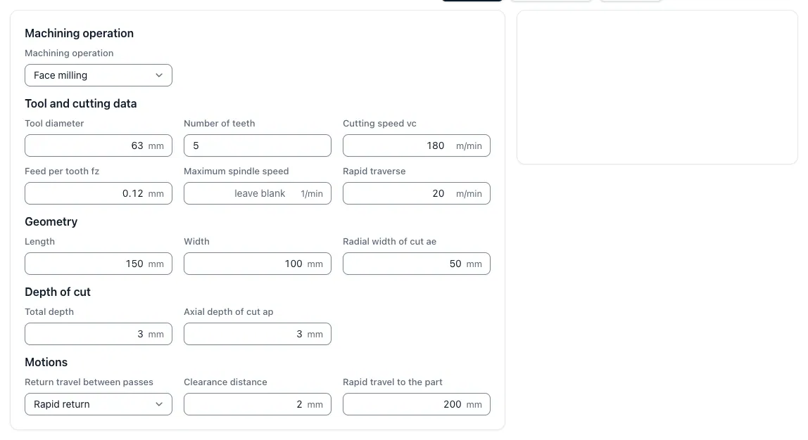
| Milling | t = L × i vf with vf = n × z × fz |
Tool path per track plus access and overflow | Calculate milling time |
| Drilling | t = L ÷ (n × f) |
Drill depth plus tip length and start-up | Calculate drilling time |
| Threaded drilling | t = 2 × L ÷ (n × P) |
Thread depth plus start, feed and return at the same speed | Core hole and thread |
At constant cutting speed the speed changes with the diameter; a fixed speed in the time approach is then an approximation. If the threaded drill runs back faster than it cuts forwards, the return rate decreases accordingly.
Tool change time
The tool change time per part has two parts. The scheduled part is the number of tool changes per part times the chip-to-span time of the machine, i.e. the time from the last cut of the old to the first cut of the new tool. The wear-related part is created because cuttings are exchanged after the end of their service life: the operating time per part divided by the service life results in the change per part, sometimes the time for an exchange.
t_W = change per part × t_span-to-span + γ (t_intervention γ T) × t_tausch
A calculation example with assumed values: Six tools per part at 6 seconds chip-to-span time results in 0.6 minutes. A grinding cutter with 8 minutes intervention per part and 40 minutes service life is exchanged every five parts; at 2 minutes per exchange the 0.4 minutes per part. Together 1.0 minute tool change time per part occur. The tool tool change time of the app calculates both parts, the service life itself shows calculate service life.
From peak time to piece and order time
For the preliminary calculation, rapid paths, start-up and start-up, touch-on, workpiece handling, chip removal and process-accompanying tests are then added. Simplified is t_piece = ̄t_main + ̄t_along with + t_nozzles ÷ N, where N denotes the lot size.
For 16 minutes main time, 5 minutes side time including tool changes and 90 minutes set-up time for 30 good parts, the calculation results in 24 minutes per part. For the whole job is T = t_Rüsten + N × (t_Main + t_Aid) = 90 + 30 × 21 = 720 minutes, i.e. 12 hours machine occupancy. How set-up time, time per unit and distribution time are assembled at the order time, explains Calculate order time.
Limits of the invoice
Whether this value fits the job depends on the input. CAD geometry provides shape and dimensions, but usually does not provide complete information on material, tolerances, surface, clamping concept or test plan. Machine, tool elongation, cooling and operating concept also affect the achievable time. Therefore, the calculated processing time is professionally released as a comprehensible plan value and then checked with actual times from comparable orders.
If you do not want to set up the times for the work itself: Fully automatic calculation from drawing and CAD (Pro) derives operations and times from drawing and CAD model and presents them as a calculation design; each value remains comprehensible and you release the design.
Key points
Processing time is explained in such a way that inputs, procedures, effects and limits in the CNC calculation remain comprehensible.
- Main time per operation: Turning, milling, drilling and threading are expected with their own formula and their own cutting data.
- Separately record tool changes: Planned changes per part and wear-related changes from the service life result in the change time.
- Spread the set-up time over the lot: One-off expenditures are divided by the number of good parts and added per piece.