Type of fit according to ISO 286 with limit dimensions and calculation distance
What does fit mean?
A fit describes how two parts interact with the same nominal dimensions, usually a bore and a shaft. Whether they move freely, can be attached with light force or sit firmly depends on where their tolerance fields lie. Fits according to ISO 286, in Germany as DIN EN ISO 286, describe this with a short sign such as H7/g6: on the left the field of the bore, on the right the shaft.
Each tolerance field consists of a letter and a number. The letter determines the position to the zero line, i.e. the nominal dimension, the number the basic tolerance degree IT and thus the width. Capital letters stand for holes (inside dimensions), lower letters for shafts (outside dimensions). H means a lower dimension of zero at the bore, h for the shaft an upper dimension of zero. The width grows with the nominal dimension: IT7 is 15 μm wide at Ø 10 mm, 21 μm at Ø 25 mm and 46 μm at Ø 200 mm. All dimensions per field and nominal dimension range are in the ISO tolerance table.
What is a match?
A match is a fit, where the hole is larger than the shaft even in the worst case. Even the smallest hole hits the largest shaft, and it remains game.
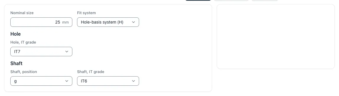
For Ø 25 H7/g6 the bore is between 25,000 and 25,021 mm, the shaft is between 24,980 and 24,993 mm. The minimum game is 25,000 − 24,993 = 7 μm, the maximum game is 25,021 − 24,980 = 41 μm. Typical applications are sliding and guide seats. H7/h6 is the limit case with a minimum game of zero.
| Match | Ø 20 mm | Ø 50 mm | Ø 100 mm | Typical use |
|---|---|---|---|---|
| H7/h6 | 0 to +34 μm | 0 to +41 μm | 0 to +57 μm | Sliding seat without appreciable play, hand-available |
| H7/g6 | +7 to +41 μm | +9 to +50 μm | +12 to +69 μm | Sliding seat for guided movements and bearing seats |
| H7/f7 | +20 to +62 μm | +25 to +75 μm | +36 to +106 μm | Running seat with room for a lubricating film, for example in sliding bearings |
The values call minimum to maximum play, calculated from the dimensions according to ISO 286. A nominal dimension belongs to the range "over ... up to ...: Ø 50 mm counts to over 30 to 50 mm, Ø 100 mm to over 80 to 120 mm.
What is a transitional fit?
A transition fit is a fit, in which depending on the actual dimension of borehole and shaft play or excess can occur. The tolerance fields overlap.
For Ø 25 H7/k6 the shaft is between 25,002 and 25,015 mm. If the smallest hole hits the largest shaft, 15 μm is oversized; if the largest hole hits the smallest shaft, 19 μm remains in play. Such seats center parts and can usually be joined and released with light force.
| Match | Ø 20 mm | Ø 50 mm | Ø 100 mm | Typical use |
|---|---|---|---|---|
| H7/js6 | −6.5 to +27.5 μm | −8 to +33 μm | −11 to +46 μm | mostly game, easy joining with good centering |
| H7/k6 | −15 to +19 μm | −18 to +23 μm | −25 to +32 μm | centering seat, available with light force and removable |
| H7/m6 | −21 to +13 μm | −25 to +16 μm | −35 to +22 μm | firmer seat, excessive, joining with force |
| H7/n6 | −28 to +6 μm | −33 to +8 μm | −45 to +12 μm | fixed seat close to the overpass, joining with press usual |
Negative values mean excess. The column "typical use" describes the tendency from the numbers; which seat is used determines the function of the component.
What is an excessive pass (press pass)?
An oversize fit is a fit, in which the shaft is larger than the bore even in the worst case. In colloquial terms, it is called press fit or press seat.
For Ø 25 H7/p6 the shaft is between 25,022 and 25,035 mm. The smallest excess is 25,022 − 25,021 = 1 μm, the largest 25,035 − 25,000 = 35 μm. It is fitted with a press, by heating the bore or cooling the shaft. Whether the connection safely transmits a torque is a separate design; the press band calculator of the app estimates joint pressing and transferable torque.
| Match | Ø 20 mm | Ø 50 mm | Ø 100 mm | Typical use |
|---|---|---|---|---|
| H7/p6 | −35 to −1 μm | −42 to −1 μm | −59 to −2 μm | Press seat for permanent connections, design of the press association separately |
The table does not contain other oversized fields such as r6 or s6 because they are not stored in the data of this website and the fit calculator.
Calculate fit type over cross
The fit type follows from two differences, each describing the most unfavourable pairing. The minimum game compares the smallest hole to the largest one, the highest game the largest hole to the smallest one. With the dimensions ES and EI of the hole as well as it and an ei of the shaft apply:
- Minimum game = EI – it
- Maximum game = ES − e
- Both results positive or zero: match. Both negative: oversize fit. Different signs: transition fit.
Example Ø 25 H7/k6, step by step: The hole H7 has ES = +21 μm and EI = 0, the shaft k6 has it = +15 μm and ei = +2 μm. The minimum game is 0 − 15 = −15 μm, i.e. 15 μm excess. The maximum game is 21 − 2 = +19 μm. Because the signs are different, H7/k6 is a transition fit at Ø 25 mm. The fit tolerance, i.e. the spread width, is 19 − (−15) = 34 μm and corresponds to the sum of the two tolerances IT7 and IT6 (21 + 13 μm).
Passing system: single bore and unit shaft
A fitting system determines which part is used as a fixed reference size: In the unit bore, the bore is always H, in the unit shaft, the shaft always h. The desired fit is then created via the other part.
In practice, the system dominates unit drilling. This is useful in manufacturing technology, because drilling is often made with dimensioned tools such as reamers, while shaft dimensions can be flexibly rotated or sanded. The system unit shaft remains useful where drawn rod material is used in h9 or h11 without post-processing or where several different seats lie on a continuous shaft.
Select fit and rate in the calculation
The selection follows the function: Should a part move, center or transfer a moment? Production and costs only come after that. A fit concerns a single feature and does not cost the whole component at all. The effort is made concretely: additional levelling, rubbing or fine drilling instead of drilling, if necessary grinding or honing, more stable tension, temperature guidance with narrow tolerances as well as a suitable measuring medium and the associated measuring time. In addition, form and position tolerances, reference system and surface information are to be tested – a hole H7 with required cylindricality is a process other than a pure dimensional tolerance.
The match calculator according to ISO 286 provides boundary dimensions, play and fit type for each nominal dimension up to 500 mm; the dimensions of all common check fields are in the ISO tolerance table. The page calculate tolerance shows how the maximum and minimum dimensions of a single measure are created. Whether a match indication is valid and complete on the drawing belongs to the examination of the manufacturing drawing prior to the offer.
Key points
Passages are explained in such a way that inputs, procedures, effects and limits in the CNC calculation remain comprehensible.
- Separate letter and number: The letter determines the position of the zero line, the number of the IT degree and thus the width of the tolerance.
- Select system consciously: Unit borehole is the rule case; unit shaft is worthwhile with drawn rod material.
- Evaluate effort per feature: A fit affects an area, not the component – it includes finishing, rubbing and measuring.