CAD file formats and their content
A CAD file format determines which information a file carries: exact surfaces of a volume model, an approximate triangle network, 2D lines or the complete design history of a system. For production, it counts whether the geometry is dimensionally accurate and whether the receiving program can read it.
Comparison of CAD file formats
| Format | Ending | Contents | suitable for | Evaluable in the app |
|---|---|---|---|---|
| STEP | .stp, .step | exact area and volume geometry, depending on export with assembly structure | Exchange of 3D models, production and calculation | Yes, free of charge |
| IGES | .igs, .igs | Surfaces and curves, older neutral format | Exchange with older systems | no, export as STEP |
| STL | .stl | Triangular network of the surface without exact surfaces | 3D printing, visualization, volume and surface estimation | Yes, free of charge |
| DXF | .dxf | 2D contours of lines, arches and polylines | Laser and water jet cutting, 2D cuttings | Yes, free of charge |
| DWG | .dwg | native drawing format of common 2D CAD systems | Drawing exchange between compatible systems | no, export as DXF or PDF |
| JT | .jt | lightweight 3D representation, depending on export with exact geometry | Visualization and data exchange in the design | no, export as STEP |
| Native CAD Formats | Depending on the system | complete model with design history and parameters | Work in the same CAD system | no, export as STEP |
| PDF drawing | technical drawing with dimensions, tolerances and material | Drawing on the model, offer and test | AI drawing analysis in Pro | |
| G-Code | .nc, .tap, .gcode | NC program with driving commands, no CAD format | Machine; runtime of an existing program | yes, supported commands, free |
The column "Evaluable in the app" corresponds to the File Formats page. A supported format does not guarantee a complete result; units, drawing level and hints on the result must be checked on the original file.
Neutral and native CAD formats
Native formats store a model as it was created in the CAD system, with design history, parameters and links. Other systems often do not read it or only partially. Neutral formats such as STEP or IGES only transmit the result, the geometry and depending on the export component structure, colors and metadata, and are therefore the usual way between construction, customer and manufacturing.
For a calculation the geometry is sufficient. The public web app does not process native CAD files as well as IGES, JT and DWG directly; a 3D model is exported as STEP or STL, a 2D contour as DXF and the drawing as PDF.
STEP AP203, AP214 and AP242
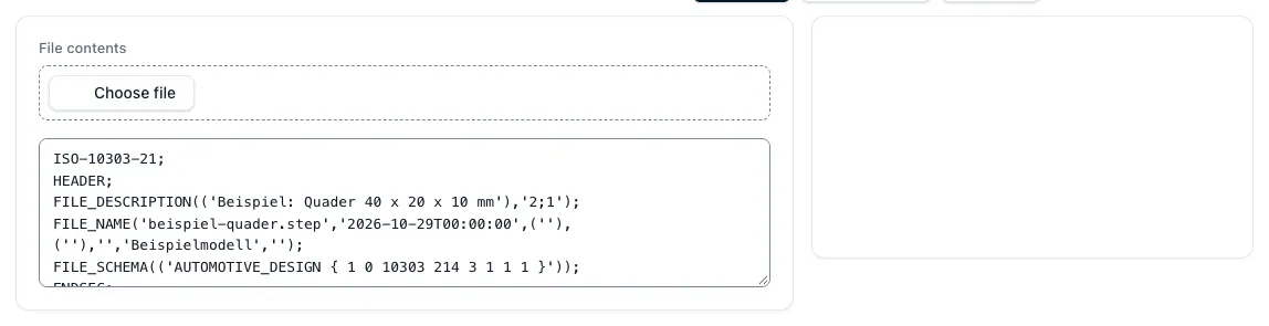
STEP files are available in various application protocols. AP203 and AP214 are most common in manufacturing and can transmit both exact volume geometry; they differ mainly in additional product structure, color and metadata. AP242 is the younger protocol for the exchange of 3D design data.
The file extension does not reveal the log; it is in the head of the file. What information a specific file actually contains depends on the exporter and is checked before use. More information on the STEP AP203 and AP214 page in manufacturing practice.
STEP-NC is not a CAD exchange format
The search for "NC STEP" often involves STEP-NC, a separate data model for NC processing data that describes work steps and editing features instead of driving commands. With the CAD exchange format STEP for models, it has the name in common, not the purpose; the app evaluates STEP models, not STEP-NC data.
Simplified models and networks
Simplified CAD models remove holes, threads, radii or threads, for example to protect design knowledge or keep files small. For a calculation, this is tricky: missing holes and threads change the characteristic counting and thus the times, and a volume without holes results in too high a chip volume. A simplified model therefore always belongs together with the complete drawing in the request.
A STL network approaches curved surfaces with triangles. Surface and volume can be estimated from it, exact bore diameters and tolerances cannot be estimated. STEP is therefore the better choice for production and calculation if both are available.
Which file to send for a calculation
For a turning or milling part: the 3D model as STEP and the drawing as PDF, both with the same revision level. For a sheet metal or laser part: the contour as DXF in original scale and the drawing as PDF. An existing NC program can prove the running time as G code.
From these documents the geometry is automatically read, and each derived value remains verifiable with its source: dimensions and volume from the model, material and tolerances from the drawing. The fully automatic calculation from drawing and CAD creates a complete calculation draft from it in Pro, which you check and release. Pro is available and will be unlocked on request; the price will be indicated on request.
Questions and answers
Which CAD format is suitable for production?
For 3D parts, STEP is usually used because it transmits exact surfaces and is read by almost all CAD and CAM systems. For 2D cuts DXF, for technical drawing PDF.
What is the difference between STEP and STL?
STEP describes exact surfaces and volumes, STL only a network of triangles that approximates curved surfaces. STL can be used to estimate surface and volume, but not to read exact bore diameters.
Can the app open native CAD files?
No. The public web app does not process native CAD files as well as IGES, JT and DWG directly. Export the model as STEP or STL, contours as DXF and drawing as PDF.
Is STEP-NC the same as a STEP file?
No. STEP-NC is a data model for NC processing data, a STEP file from CAD transmits the component geometry. The app evaluates STEP models, not STEP-NC data.