Milling effort from geometry, drawing and operating data
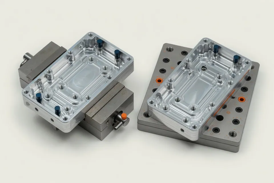
For the precalculation of a milling part, component volume and material alone are not sufficient. The starting point is an evaluable CAD model in the existing format, the associated technical drawing, stock acceptance and lot size. The geometry can be seen, among other things, external contours, pockets, heels, holes and accessible surfaces. The drawing complements the requirements that are often lacking in the model: dimension and shape tolerances, fit, surfaces, threads, covers and special test features.
In the next step, a plausible production sequence is created. The calculator assigns suitable processing methods and considers whether tarpaulining, grinding, scraping, finishing, drilling, sinking or threading are required. It is also crucial to determine how many stresses are required and which areas can be reached with the intended machine. Tool stock, cutting values, travel distances, change and touch times as well as operational rules are incorporated into the time evaluation. The specialist confirms critical characteristics and corrects suggestions if the clamping position or manufacturing strategy is to be chosen differently.
The visible output connects operations with main time, side time and set-up part. For several quantities it is possible to understand how fixed set-up costs and variable processing times are distributed. Costs are then incurred from the stored machine and personnel sets as well as material, tools and, if necessary, external services. Deep pockets, large cutting volumes, long tools, many tool changes, hard-to-reach surfaces and quality requirements, which cause additional levelling or test steps, are particularly relevant.
A CAD-based calculation does not replace a CAM system. It does not create a shared tool path and does not confirm freedom of collision or secure clamping agents. In complex free-form surfaces, difficult-to-reach areas or non-validated multi-axis strategies, a targeted professional examination is required. Therefore, a pilot will jointly clarify which milling parts, machines and processing methods form the relevant application area and which data are available today for a comprehensible calculation.
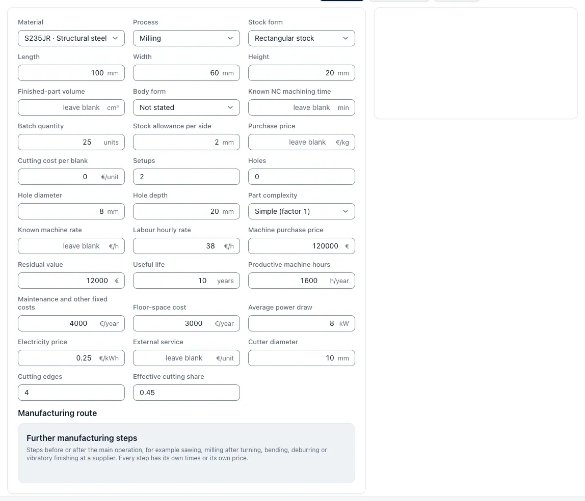
The calculation path with time portions and an example in one and three clampings shows Calculation Milling parts. In Pro, the precalculation from drawing and STEP model is fully automatic as a calculation design, which you check and release; for more information see Full automatic calculation from drawing and CAD.
Result of the application
In "Precalculating milling parts from CAD and drawing", existing data are combined with a clear decision and a visible result.
Connect geometry and drawing
Bags, holes and surfaces are evaluated together with tolerances and surfaces.
Concreteize production sequence
Tensions, roughing, finishing, drilling and testing form a verifiable process.
Put Time Model Right
The precalculation provides a basis for the offer, but no CAM simulation.