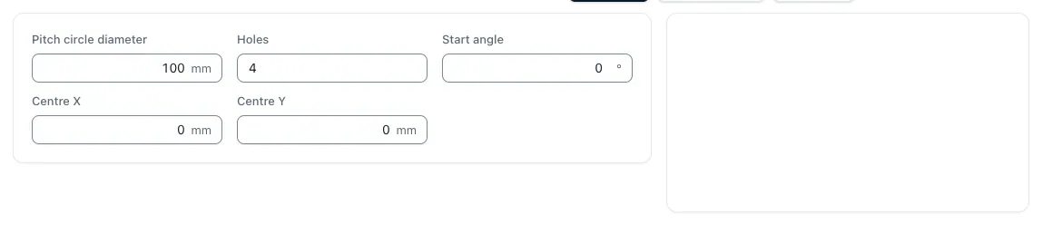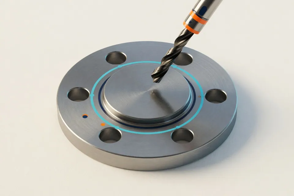
The calculator distributes the holes evenly across the circle, shows each XY coordinate and generates a simple G81 program. Safety and control parameters remain visible and must be checked before use.
Formulas
Δα = 360° ÷ zAngular distance
Even distance from the number z of holes.
Xi = X0 + R × cos(αi)X-Coordinate
Circular center point X0 plus horizontal radius portion.
Yi = Y0 + R × sin(αi)Y-coordinate
Circular center point Y0 plus vertical radius portion.
αi = α0 ± i × ΔαDrilling sequence
Start angle α0 and selected direction of rotation determine the order.
Six holes on Ø 80 mm around X0/Y0 = 0
Starting angle 0°, counterclockwise, R-plane 2 mm, drilling depth −12 mm.
- Radius = 80 240 mm
- Angular distance = 360 - 660°
- Hole 1 at 0°X 40,000 / Y 0,000
- Hole 2 at 60°X 20,000 / Y 34,641
- Hole 4 at 180°X −40,000 / Y 0,000
ResultThe computer lists all coordinates and creates a copyable G81 program example.
Before real processing, the program must be simulated and released with the concrete control, the post processor and the voltage.
Generated code always needs real release
The example makes geometry and order quickly usable. However, it does not know your control or tool length, collision space, units, clamping devices or operational release process.
Questions and answers
How do you calculate the coordinates of a hole circle?
For each hole, X = X0 + R × cos(α) and Y = Y0 + R × sin(α) apply. The angular distance is 360° divided by the hole number. Start angle and direction of rotation determine the order.
Which G-code does the computer generate?
The computer creates a simple ISO example with absolute dimensions, XY level, workpiece zero point G54 and drill cycle G81. Control, postprocessor, units, tool data and safety logic may differ from this.
What's the R-level for?
R is the retreat plane of the drilling cycle. It must be securely located over workpiece, clamping agents and interference contours without creating unnecessarily large empty distances.
Can I load the code directly to the machine?
No. Check and simulate the code first in the intended control or CAM environment. Zero point, level, units, tool, speed, feed, depth, sign and withdrawal must fit the real machine.
How do I change the order of the holes?
Over start angle and direction of rotation. Counterclockwise the calculator increases the angle, clockwise it is reduced per bore.