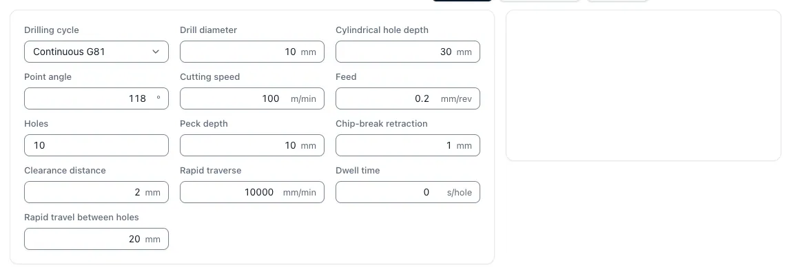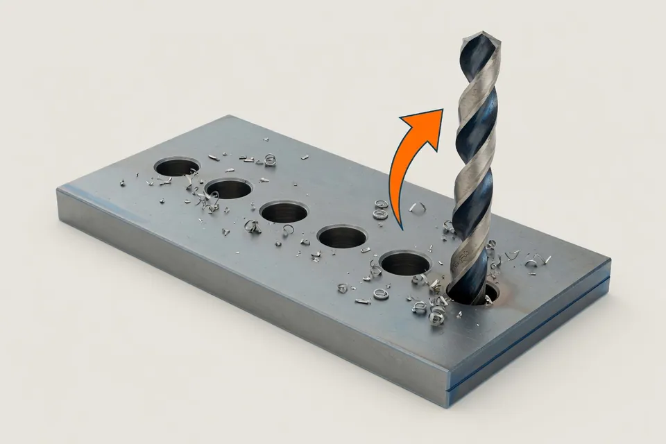
Drilling time is calculated from the entire feed path divided by the feed speed. The app's tool takes into account drilling depth, peak length from the peak angle and start-up distance and calculates cutting and side-time on all drill holes per component.
Formulas
n = (vc × 1000) ÷ (π × d)Speed
As with any rotating tool, here with the drill diameter.
vf = n × fFeed speed
The feed per revolution f is multiplied by the speed.
l_Spitze = d ÷ 2 ÷ tan(σ ÷ 2)Peak length
σ is the tip angle, usually 118 or 140 degrees.
t = (L + l_Spitze + l_Anlauf) ÷ vfTime per hole
The entire feed path divided by the feed speed.
Twelve core holes for M10 in mild steel
Drills Ø 8.5 mm, vc 90 m/min, feed 0.18 mm/U, drilling depth 25 mm, tip angle 140 degrees, 3 mm start, 4 seconds positioning time per bore.
- RPM n = 90 × 1000 (π × 8.5)3,370 1/min
- Feed speed vf = 3.370 × 0.18607 mm/min
- Point length = 8,5 י 2 י tan(70°)1.55 mm
- Distance per hole = 25 + 1.55 + 329,55 mm
- Cutting time per hole = 29.55 ÷ 6070,05 min
- Add 4 s positioning time per hole0.07 min
- Total time per hole0,115 min
- Twelve holes × 0.115 min1,38 min
ResultApproximately 1.4 minutes of drilling time per component – a good half of it is incidental time.
Sinking, threading and deburring are not yet included in this list. This is precisely the proportion that is regularly underestimated in drilling-rich components.
Reference values for drilling with solid carbide
Start values with inner coolant supply and stable clamping. The data of the tool manufacturer are binding.
| Material | vc (m/min) | f per revolution | Note |
|---|---|---|---|
| Aluminium | 150–350 | 0,10–0,30 mm | High amount of chip, good removal necessary |
| Structural steel S235 / S355 | 80–130 | 0,15–0,30 mm | Good-natured, standard case |
| Remuneration steel C45 / 42CrMo4 | 70–110 | 0,12–0,25 mm | Beware of withdrawal |
| Stainless steel 1.4301 / 1.4404 | 50–90 | 0,10–0,20 mm | Constant feed against cold solidification |
| Grey cast iron EN-GJL-250 | 80–140 | 0,15–0,30 mm | Short-range |
| Titanium Ti-6Al-4V | 25–50 | 0,08–0,15 mm | Heat and chip removal critical |
From about 3 × d depth, demining cycles or deep hole drills are to be expected; the time increases disproportionately.
Many small holes hit a big bag
Drilling works over their number. Starting, positioning, drilling, sinking and deburring sum up – therefore each drilling group is included in the time calculation as its own position.
Questions and answers
How do you calculate the drilling time?
The drilling time is obtained from the entire feed path divided by the feed speed: t = (drill depth + peak length + start) ÷ (n × f). N is the speed and f is the feed per revolution. For one component, the time is multiplied by the number of holes and supplemented by positioning and tool changing times.
What is the peak length and why does it count?
The drill tip is conical. To complete a hole at full depth, this cone has to be additionally passed through. The tip length is d ÷ 2 ÷ tan(peak angle ÷ 2) – with a 8.5 mm drill with 140 degrees approximately 1.5 mm, at 118 degrees approximately 2.6 mm. In through drilling it is added to the drill path.
Which feed is common during drilling?
The reference value is f 😉 0.02 × d to 0.03 × d per revolution for solid carbide in steel, for HSS drills rather less. For a 8.5 mm drill, this is about 0.17 to 0.25 mm/U. The manufacturer's specifications for material, drill type and cooling are binding.
From what depth is the machine decoupled?
From about three to five times the diameter, the chip removal significantly worsens. Then, the machining cycles are worked with or changed to deep hole drills with inner coolant supply. Both significantly extend the machining time and belong in the calculation.
Why are drilling in the calculation so important?
Because their number is multiplied. Each hole costs starting, positioning, drilling, and often sinking or deburring. In the case of well-rich components, this proportion often exceeds the time of contour processing, although the deburring volume is small.