Rotation time from feed path and feed speed
Formula for turning time during longitudinal turning
For a straight feed path, t_h = L ÷ (n × f). L is the full feed path in millimetres, n is the feed speed in revolutions per minute and f is the feed in millimetres per revolution. The product n × f is the feed speed in mm/min; the time is given in minutes. The speed is assumed here as known; as it is obtained from cutting speed and diameter, calculate the feed rate.
With several equally long cuts with the same cutting data, the time is multiplied by their number. Different cuts get their own values. Grinding, finishing, drilling, threading and cutting are therefore not combined with a single middle feed.
Example with two longitudinal sections
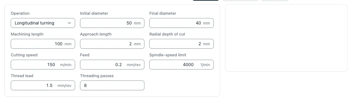
A freely chosen example uses 80 mm machining length as well as a total of 4 mm feed and overrun. At 1,200 1/min and 0.20 mm feed per revolution, the feed speed is 1,200 × 0.20 = 240 mm/min.
A cut thus takes 84 י 240 = 0.35 min, i.e. 21 seconds. Two identical cuts take 0.70 minutes or 42 seconds of main time. These values show the calculation path; the cutting data are not a recommendation for a particular material or tool.
The main time calculator Rotate calculates the entered paths and cut data. The cut data for turning help to assess speed and feed together.
Several notifications and effective way
With an assumed reduction in diameter from 50 to 42 mm, 4 mm must be removed radially. With a maximum of 2 mm radial delivery, two grinding cuts would be necessary. A intended level of finishing can change the division. The number of cuts therefore follows from the machining strategy, not only from an automatically rounded ratio.
The feed path contains start-up and overflow only to the extent that they are actually driven with feed. An rapid response is set with its own time. Tool withdrawal and delivery are additionally recorded if they are not already included in the measured side-time.
Rotate the plan and keep cutting speed constant
The tool runs radially when the plan is turned. The path is half the difference in diameter, supplemented by necessary access and exit paths. At constant speed, the formula L ÷ (n × f) remains applicable, although the cutting speed changes during the cut.
At constant cutting speed, the speed increases with a smaller diameter until the specified speed limit is reached. An approach with the speed at the outer diameter does not fully describe this course. The app offers its own tool for constant cutting speed. Clamping conditions and released machine limits remain decisive.
From peak time to time per piece
If we add 0,70 minutes of peak time by 0,80 minutes of incidental time, 1.50 minutes of recurring cycle time per part will be generated. 40 minutes of set-up will be distributed over another 2,00 minutes in 20 parts. The rated time will then be 3,50 minutes per piece; the lot will need 40 + 20 × 1,50 = 70 minutes.
This order time is not a delivery date: Queue, external processing and transport can additionally extend the lead time. The time terms and the cost calculation explain the demarcation. For the price, material, suitable hourly sets, tool and external performance costs are then added in the turned part calculation.
Key points
Rotation time is explained in such a way that inputs, procedures, effects and limits in the CNC calculation remain comprehensible.
- Completely detecting ways: Processing length, start-up and overflow result in the path for each cut.
- Keep constant cutting speed: With changing diameters, a fixed spindle speed is only an approximation.
- Add time types separately: Tool changes, handling and measuring are part of the incidental time; setups are distributed over the lot.