Read out technical drawings structured for CNC calculation
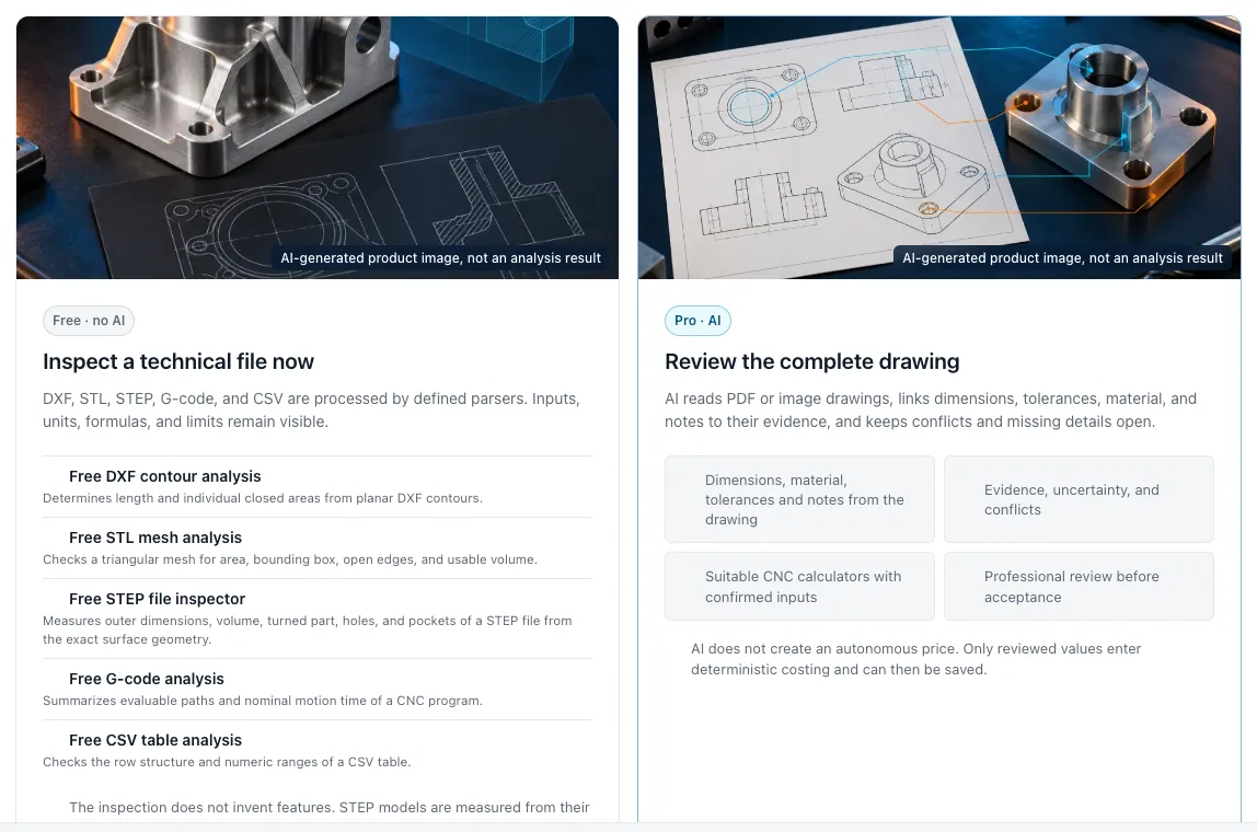
A technical drawing is read out for the CNC calculation by recording document data, dimensions and quality requirements in a structured manner and assigning them to their component characteristic. In the title block there are often part number, revision, material, scale, general tolerance and modification notes. Views, cuts and hints contain local dimensions, fit, thread, roughness values as well as shape and position tolerances. These data complement the geometry of the 3D model and can significantly change the manufacturing and testing effort.
The process starts with document quality. Vector-based PDF files can usually be captured more clearly than inclined or low-resolution scanned drawings. Sheet format, orientation, scale and the relationship of several sheets must be preserved. After that, title block, general hints and dimensions are processed separately. A recognized entry such as H7 is only usable when nominal diameter and associated bore are fixed. A roughness symbol applies only to the surfaces to which it actually refers.
For critical information, original cut-out, recognized value, unit and location should remain verifiable. Low detection security can arise from superimposed lines, unusual fonts, poor resolution or rare symbol combinations. Plausibility rules reveal additional problems, such as contradictory units or inconsistent revisions of drawing and CAD model. Such hints support the examination, but do not decide any technical contradictions.
The benefits for the calculation are generated by the translation into concrete work steps. A tight bore tolerance can require pre-drilling, rubbing and measuring. Low roughness can trigger a simple procedure or an additional procedure. A situation request may affect uplifting and testing concept. These consequences are assigned to the affected feature, not as a flat-rate time mark on the entire component. Handwritten additions, incomplete scans and operational special characters remain limit cases that a qualified production planner must release.
Key points
Drawing is explained in such a way that input, procedure, effect and limits remain comprehensible in the CNC calculation.
- Clearly assign the document: Part number, revision, scale, sheet and state of change are secured before the feature evaluation.
- Locate requirements: Recognised values remain associated with symbol, view and affected geometry to maintain their manufacturing reference.
- Insecure to be checked: Badly readable, incomplete or contradictory information is marked and not calculated unchecked.