Nominal dimension, dimensions, limits and tolerances
The nominal dimension is the measure on the drawing, for example Ø 40. The dimensions indicate how far the actual dimension may deviate from it: the upper dimension upwards, the lower one downwards, each with signposts. For boreholes they are marked with ES and EI, for shafts with it and ei.
From nominal dimensions and dimensions, the limit dimensions follow, i.e. the maximum and minimum dimensions. Tolerance is the width between and thus always positive. It is independent of whether the field is above, below or around the nominal dimensions.
Maximum dimension = nominal dimension + upper dimension Minimum dimension = nominal dimension + lower dimension T = maximum dimension – minimum dimension
Tolerance of ISO short characters or dimensions
Which calculation path and which tool of the app fits depends on how the tolerance is written.
Which tolerance indicates which calculation path needs
| Marking on the drawing | Example | Calculating path | App tool |
|---|---|---|---|
| Free dimensions | Ø 40 +0,05/−0,02 | Nominal dimensions plus upper and lower dimensions | Limit dimensions |
| ISO tolerance field | Ø 25 H7, Ø 25 h9 | Basic tolerance IT and basic dimensions according to ISO 286 | Fit, IT degree |
| No tolerance | Ø 60 with ISO 2768-m in the title block | General tolerance according to ISO 2768-1 | General tolerance on this website |
ISO table values are given in the ISO tolerance table, general tolerances on the General Tolerances page according to ISO 2768.
Example calculation with dimensions
On the drawing is Ø 40 +0.05/−0.02. The maximum dimension is 40 + 0.05 = 40.05 mm, the minimum dimension 40 − 0.02 = 39.98 mm. The tolerance is 40.05 − 39.98 = 0.07 mm.
For the CNC program and tool correction, the tolerance center is often the better target value than the nominal dimension: it is here at 40,015 mm, symmetrically written 40,015 ± 0,035 mm. If you produce on the middle, tool wear and measurement uncertainty leave room for both sides.
Tolerance mean = (maximum + minimum) 2
Tolerance from an ISO tolerance field such as H7
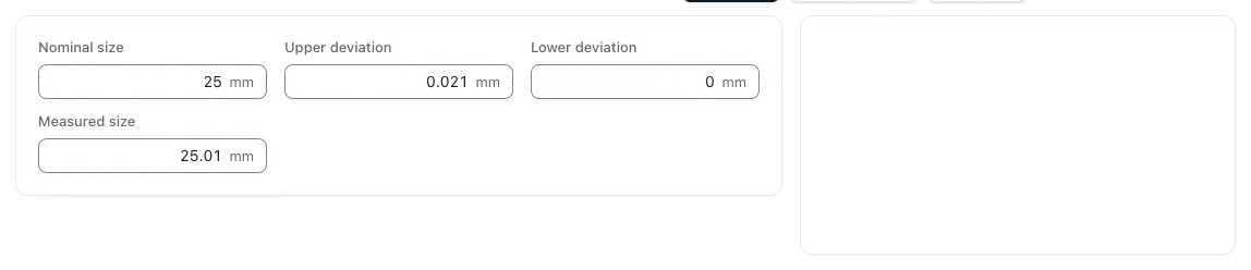
In an ISO tolerance range according to ISO 286, the number specifies the width, the IT degree, and the letter specifies the position to the nominal dimension. For Ø 25 H7, IT7 is 21 µm wide in the range over 18 to 30 mm, and H means lower tolerance zero: the hole may be between 25.000 and 25.021 mm.
For a shaft Ø 25 g6, IT6 is 13 μm wide, the upper dimension of g is −7 μm in this range. Thus, the lower dimension is −20 μm and the shaft is between 24,980 and 24,993 mm. As borehole and shaft together result in a game or oversize, the fit calculator calculates.
T = ES − EI (bore) T = it − ei (wave)
Wave tolerances h9 and h11
At h, the upper dimension is zero, so the shaft can only be smaller than the nominal dimension. The number again determines the width: For Ø 25 h9 it is 52 μm, the shaft is between 24,948 and 25,000 mm. For Ø 25 h11 it is 130 μm, i.e. between 24,870 and 25,000 mm.
h9 and h11 often stand in moderations that are not applied or only sit loosely, and are typical delivery states for drawn blank steel. Whether a semi-finished product meets a dimension without machining depends on the delivery state that is on the order.
Dimensions without tolerance
If there is no tolerance in a measure, the general tolerance is from the title block, usually according to ISO 2768-1. In tolerance class m a measure of 40 mm may vary by ±0.3 mm, the limit dimensions are 39,7 and 40,3 mm. If this note is also missing, this is a question for the quotation processing.
Exercises with solution
Three tasks, as they occur most frequently in drawings; the solution follows directly.
- Hole Ø 30 H7: According to ISO 286, IT7 is 21 μm wide in the range of 18 to 30 mm, H means lower dimension zero. Solution: Limit dimensions 30,000 and 30,021 mm, tolerance 21 μm.
- Shaft Ø 50 −0.025/−0.050: upper limit 50 − 0.025 = 49.975 mm, lower limit 50 − 0.050 = 49.950 mm. The tolerance is 0.025 mm, with a midpoint of 49.9625 mm.
- Dimensions 60 mm without tolerance, in the ISO 2768-m title block: For more than 30 to 120 mm, the standard applies in class m ±0.3 mm. Solution: limit dimensions 59.7 and 60.3 mm, tolerance 0.6 mm.
Tolerances in a dimensional chain
If several tolerated dimensions are in a row, their tolerances add up completely in the worst case. Three dimensions of ±0.1 mm each result in ±0.3 mm for the total dimension. If the individual dimensions are scattered independently of each other, the statistical sum is smaller: The root of the sum of the squares here results in approximately ±0.17 mm.
The function of the component decides which consideration is allowed. The tolerance chain calculator of the app shows both values side by side.
T_worst = T₁ + T₂ + … T_stat = √(T₁² + T₂² + …)
What a narrow tolerance in manufacturing means
A smaller tolerance rarely extends the actual cutting time, but the steps around it: an additional levelling with defined dimensions, measuring and correcting, temperature-stable testing and sometimes another method. As a rough orientation, drilling with the spiral drill is for example IT10 to IT12, flat turning and flat milling with IT7 to IT9 and rubbing typically with IT7; for IT6 and narrower is often fine-turned or ground.
Questions and answers
How do you calculate a tolerance?
The tolerance is maximum minus minimum, meaning upper minus lower dimension. For Ø 40 +0.05/−0.02, this is 40.05 − 39.98 = 0.07 mm.
What is the difference between tolerance and dimension?
A dimension is the permitted deviation from the nominal dimension in one direction, with signposts. Tolerance is the width of the permitted range between both limit dimensions and always positive.
What does ±0.1 mean in one measure?
The dimensions may be 0,1 mm larger or smaller than the nominal dimensions, so the tolerance is 0,2 mm, the centre of tolerance is on the nominal dimensions.
What tolerance does Ø 25 H7 have?
According to ISO 286, the lower dimension is 0 and the upper one is +21 μm. The bore can therefore be between 25,000 and 25,021 mm, the tolerance is 21 μm.
What does h9 mean on a wave?
h9 is an ISO tolerance field according to ISO 286: upper dimension zero, width IT9. For Ø 25 mm the shaft may be between 24,948 and 25,000 mm; for h11 between 24,870 and 25,000 mm.
What if there is no tolerance at all?
Then the general tolerance from the title block applies, mostly ISO 2768-1. In class m, for example, it is ±0.3 mm for dimensions over 30 to 120 mm.
How do you calculate tolerances in a dimensional chain?
In the worst case, the individual tolerances are added. In the case of independent scattering measures, the statistical sum is smaller as the root of the sum of squares. For three dimensions of ±0.1 mm each, the ±0.3 mm in the worst case and about ±0.17 mm are statistically.