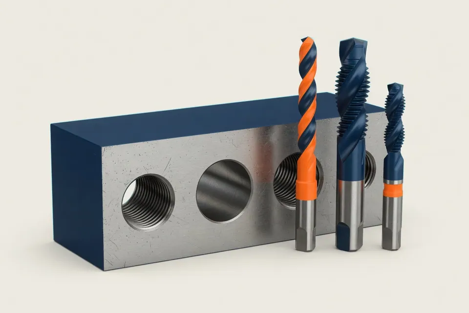
Threading process by material, component value and batch size
Three methods for an internal thread
An internal thread can be drilled, molded or milled. All three methods create the same thread profile, but differ in how the material is removed or displaced, which core hole they need and what happens when the tool fails.
Thread drilling cuts the thread with a tool whose profile corresponds to the thread. The feed is determined by the slope (vf = n × P), a thread is created in a back and forth way. This is fast and requires little programming effort. However, the thread drill works form-bound and can break in the bore, especially in bagholes with poor chip removal and tough materials.
Thread moulds replaces the material instead of cutting it. No chips are created, the thread is solidified, and the process is very stable with suitable materials. For this, the mould needs a larger core hole, which must be more accurate than when cutting, a sufficiently ductile material and a higher torque on the spindle.
Thread milling creates the thread on a helix web with a cutter that is smaller than the thread. The feed is freely selectable and is converted to the center of the tool with the circle correction. The measure can be adjusted via the radius correction, a milling cutter covers several diameters of the same slope, and breaks it rarely, remains stuck in the component. Milling usually takes longer per thread, and an NC program with helix and starting motion is necessary.
Selection by material, bore and component
| Criterion | Threaded drilling | Threading | Threading machines |
|---|---|---|---|
| Material | most machinable materials | only sufficiently ductile materials | also difficult to machine and brittle materials |
| Chips | yes, rejection critical in the baghole | none | Yes, short chips |
| Corehole | Drill diameter according to DIN 336 | larger, according to the shaper data sheet | as when cutting |
| Time per thread | Short | Short | Longer |
| Result of a tool break | Tool is often in the component | Tool is often in the component | Miller rare in the component |
| Measurement correction | No, measure by tool | No, measure by tool | yes, about the radius correction |
The table describes trends. The data of the tool manufacturer and the own experience are determined by which tool actually runs process-proof in which material.
What the choice means for the calculation
For the calculation, the complete chain per thread counts: centering or drilling, core hole drilling, sinking, threading and deburring, each with tool change and positioning distance. For a component with twenty threads, this quickly results in more minutes than for the entire contour processing, although the removed volume is minimal. A pure volume estimate therefore systematically leads to low volume estimates for well-rich components.
The process shifts the weights. Thread drilling keeps the time small, but bears the risk of losing an almost finished part by a broken thread drill; this risk belongs in the process decision, not in a lump sum. Thread milling costs more time per thread, but saves tool variety on rare gradients and reduces the reject risk on expensive parts. Thread shapes saves chips, but requires the right material and an exact core hole.
The core holes per thread size are on the side Calculating core hole, incline and voltage cross section in the Thread table M3 to M24. Speed and corrected web feed for milling calculate the side Thread milling.
Key points
Threads are explained in such a way that inputs, procedures, effects and limits in the CNC calculation remain comprehensible.
- Material first: Moulds need a ductile material; brittle and hard-to-machine materials are more likely to speak for milling.
- Construction value: The more expensive the part is when threading, the more process reliability counts over seconds.
- Calculate whole chain: Centering, core hole, sinking, threading and deburring are part of every thread.