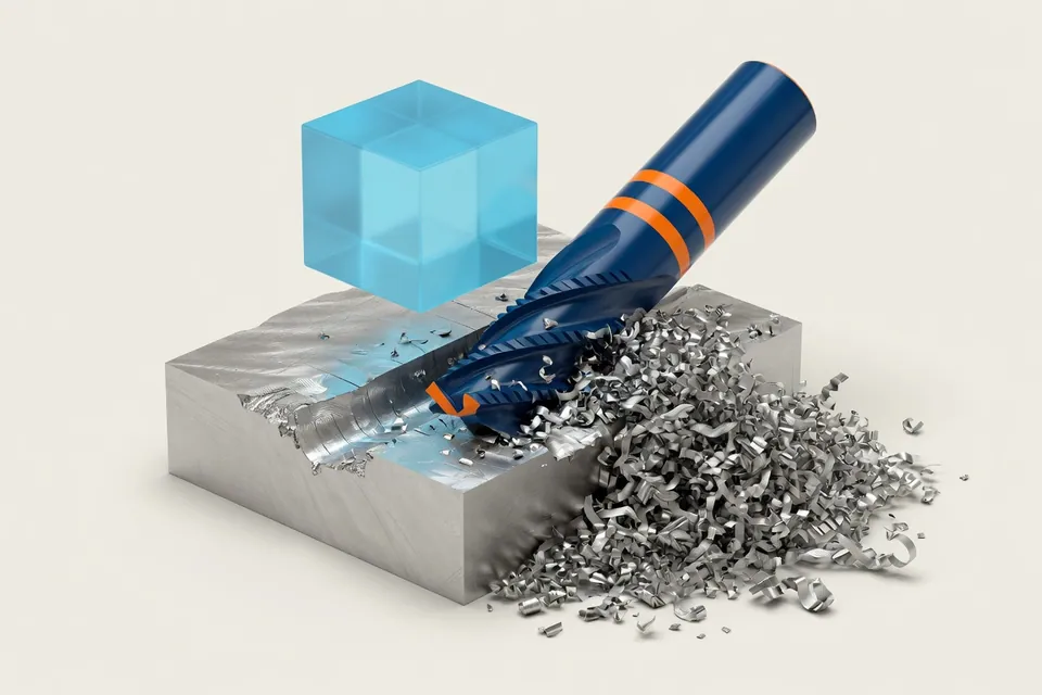
The material removal rate (also material removal rate) is the material volume, which is machined per minute, when milling Q = (ae × ap × vf) 1000 in cm³/min. With the specific cutting force follows the cutting performance, with the volume to be machined a rough machining time.
Formulas for the material removal rate
Q = (ae × ap × vf) ÷ 1000Time machining volume during milling
Q in cm³/min, ae and ap in mm, vf in mm/min.
Q = vc × ap × fTime spanning volume while turning
vc in m/min, ap in mm, f as feed per revolution in mm.
Pc = (Q × kc) ÷ 60 000Required cutting power
Pc in kW. The drive power is determined by the efficiency.
Q = (π × d² ÷ 4) × vf ÷ 1000material removal rate when drilling to the full
Drill cross section times feed speed, d in mm, vf in mm/min, Q in cm³/min.
t = V ÷ QRough cutting time
Volume V to be machined in cm³ divided by Q results in the pure machining time in minutes.
Reference values for the specific cutting force kc
Practical averages for medium chip thicknesses. For accurate performance calculations, the Kienzle equation with kc1.1 and material exponent is to be used.
| Material | kc (N/mm²) | Note |
|---|---|---|
| Aluminium AlMgSi / AlCuMg | 500–900 | Low power requirement, mostly limited in advance |
| Structural steel S235 / S355 | 1.400–1.700 | Good-natured Area for Scratch Strategies |
| Remuneration steel C45 / 42CrMo4 | 1.700–2.100 | Climbs with strength and hardness |
| Stainless steel 1.4301 / 1.4404 | 1.900–2.400 | Tough chips, high heat input |
| Grey cast iron EN-GJL-250 | 900–1.200 | Short-spanning, low power requirement |
| Titanium Ti-6Al-4V | 1.300–1.700 | In contrast, heat is rarely limiting |
| Brass CuZn | 700–1.000 | Very high removal rates achievable |
The actual removal capacity is often not limited by the spindle power, but by stability, clamping agents, chip removal and tool life.
material removal rate during drilling
When drilling into the full depth, the entire cross-section of the drill is strained. The strain volume is therefore the circular area of the drill multiplied by the feed speed. A full-hard metal drill with a diameter of 10 mm at 80 m/min rotates at 2,546 1/min; with a feed of 0.16 mm per revolution, it travels at 407 mm/min. This results in (π × 10² ÷ 4) × 407 ÷ 1000 = 32.0 cm³/min, as shown in the example on page Drilling section data.
Q = (π × d² ÷ 4) × vf ÷ 1000
High material removal rate: what limits it
A high material removal rate shortens the grinding time, but meets several limits, often before the rated power of the spindle:
- Power and torque of the spindle at actual speed; below the corner speed is less than the rated power available.
- Rigidity of tool, absorption and tension: Cracking and thin walls lead to ratters before performance is achieved.
- Span removal: Full grooves and deep pockets clog if the chips do not come out of the procedure.
- Lifetime: They shorten higher cutting values, the tool costs per part increase.
Strategies with large axial cutting depth and small radial intervention, such as trochoidal webs, distribute heat and wear over the entire cutting length and keep the procedure constant. In small radial surgery, the chip becomes thinner than the tooth feed; how much the tooth feed is raised for this shows Calculate the voltage dilution.
Machining volume and associated material removal rate during grinding
The cutting volume is the total removed volume in cm³, the material removal rate is the same per minute. When grinding, the material removal rate is usually related to one millimeter of grinding disc width and expressed in mm³ per mm and second; this related material removal rate makes discs of different widths comparable.
From material removal rate to calculation
From the volume to be cut and the material removal rate a rough grinding time is obtained; for the offer time tool paths, smoothings and non-cutting times are added, as CNC processing time shows. For milling parts this leads to calculation milling parts.
The Fully automatic calculation from drawing and CAD (Pro) derives volumes, operations and times from drawing and CAD model and presents them as a calculation design; each value remains comprehensible and you release the design.
Detachment power as plausibility test
The material removal rate is a plausibility check, not a time calculation: tool paths, levellings, non-cutting times and setups are evaluated separately.
Questions and answers
How large is the time machining volume when milling aluminium?
This depends on the cutting tool and feed speed: Q = ae × ap × vf ÷ 1000. A shaft mill with ae = 6 mm and ap = 12 mm at an assumed 2,400 mm/min in aluminum results in 172.8 cm³/min; with kc = 700 N/mm², this requires about 2.0 kW cutting performance. The same geometry with 600 mm/min in steel results in only 43.2 cm³/min. Aluminum is therefore usually limited by spindle, feed limit and chip discharge, not by performance.
What is the material removal rate?
The time machining volume Q, also called time machining volume or removal rate, is the material volume, which is machined per minute, expressed in cm³/min. It combines cutting values with power requirements and machining time and is suitable for comparing strategies and machines.
How do you calculate the time machining volume during milling?
The material removal rate is obtained from Q = (ae × ap × vf) ÷ 1000 and is expressed in cm³/min. ae is the radial working action, ap the axial cutting depth in mm and vf the feed speed in mm/min. Example: 8 mm × 3 mm × 950 mm/min result in 22.8 cm³/min.
How do you calculate the material removal rate when turning?
When turning, Q = vc × ap × f applies.With the cutting speed vc in m/min, the cutting depth ap in mm and the feed per revolution f in mm, the volume results directly in cm³/min.
How much power does the machine need for this?
The cutting power follows from Pc = (Q × kc) ÷ 60,000 in kW, with Q in cm³/min and the specific cutting force kc in N/mm². The drive power required is higher due to friction and losses: Pan = Pc ÷ efficiency, typically 0.80 to 0.90.
Why is the specific cutting force not a fixed value?
In addition to the material, kc mainly depends on the chip thickness: the thinner the chip, the higher the specific force requirement. Therefore, the Kienzle equation works with kc1.1 and an exponent. For precalculation, a medium practical value is usually sufficient.
What is the material removal rate in the calculation useful for?
It provides a quick plausibility check: From the volume to be cut and Q results in a rough cutting time. If this deviates strongly from the detailed time calculation, assumptions for intervention, feed or tool path usually do not agree.