Milling time from tool path and feed speed
Formula for the prime time of milling
The simplified formula is: t_h = L ÷ vf. L is the feed-driven tool path in millimetres, vf the effective feed-speed in mm/min. The time is given in minutes. For similar tracks and depth cuts t_h = L_Bahn × number of lanes × number of deliveries ÷ vf applies.
The feed speed shall be vf = n × z × fz: speed n in 1/min, tooth count z and tooth feed fz in mm. The speed side shows how speed and feed speed arise from cutting speed and cutter diameter. The number of cuttings on the cutter, not the cuttings in the operation at the same time, depends on the choice of suitable tooth feed, among other things, of tool, material and intervention.
Example with three milling mills and two depth assignments
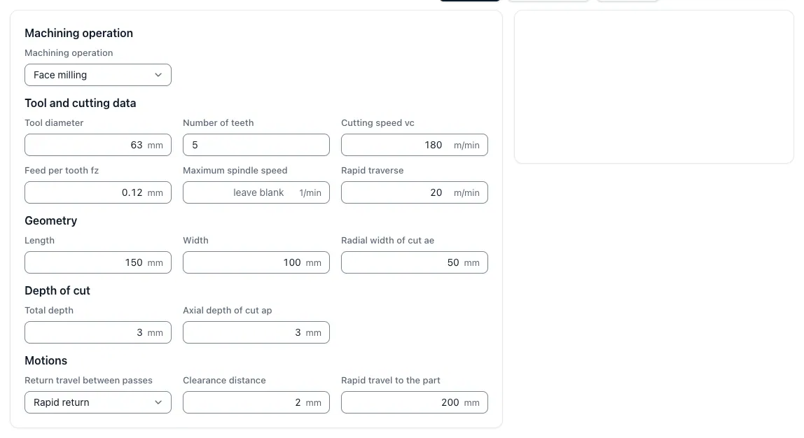
An example uses 4,000 1/min, four teeth and 0.05 mm tooth feed. This is followed by vf = 4,000 × 4 × 0.05 = 800 mm/min. With 120 mm processing length and a total of 20 mm access and overflow, the path is 140 mm per path.
Three lanes in two depth assignments each give 140 × 3 × 2 = 840 mm. The main time is 840 ÷ 800 = 1.05 minutes, i.e. 63 seconds. In addition, the necessary return paths and position changes. The numbers are a calculation example and not a general cut data recommendation.
In the Main Time Calculator Milling you can use your own paths and values. Explain the appropriate relationships between speed, tooth feed and power Cutting data Milling and the Feed calculator.
Evaluate plan milling, grooves and pockets separately
The number of webs depends on the machining width, tool diameter and web distance. The required access and overflow follows from the actual web guide. A flat-rate addition of an entire tool diameter is therefore not correct in any case.
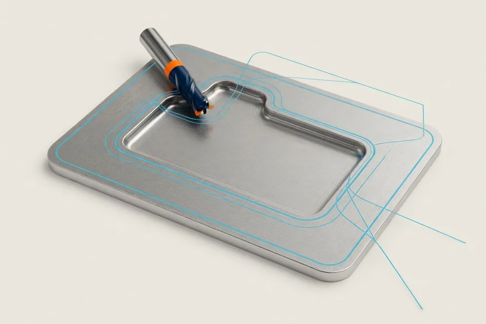
In the case of grooves, the depth assignments and possible smooth tracks count. A bag additionally requires a way to immerse, clear out and, if necessary, edit the residual material. The outer length of the bag is not equal to the entire tool path.
For curved surfaces and complex strategies, planned CAM paths or measured reference programs are the appropriate data base. Even then, rapid response, acceleration, control behavior and tool changes must fit the machine. The Guide for 5-axis milling ranks additional expenses.
Time during circular milling
When drilling a bore, the center of the tool is driven on a smaller circle than the bore: for bore diameter D and cutter diameter d, the center of the tool is π × (D − d) long. When milling a cone, it is longer with π × (D + d). The program usually programs the feed at the center of the tool, while tooth feed and cutting conditions apply at the cutting edge. To ensure that the cutting runs the planned feed, the web feed is corrected: inside vf, middle = vf, cut × (D − d) ₫ D, outside vf, middle = vf, cut × (D + d) ⇩ D.
A calculation example with assumed values: A hole Ø 30 mm is milled with a diameter of 16 mm circularly, at the cutting edge are planned 400 mm/min. The center web is π × 14 = 44.0 mm long, the programmed feed is 400 × 14 ÷ 30 = 186,7 mm/min, one orbit lasts 44.0 ◄ 186,7 = 0.24 minutes, i.e. about 14 seconds. Without correction, the cutting ran with more than twice the planned feed. The time per orbit corresponds to the bore circumference divided by the feed at the cutting edge, π × 30 ― 400.
The tool Circular feed the app calculates the correction for inner and outer circles. The same correction applies to the screw web at the Threading machines.
From milling time to complete application
If we add 0.45 minutes to the 1.05 minutes main time, 1.50 minutes of recurring effort per part. With 25 minutes set-up and 50 parts, the order time is 25 + 50 × 1.50 = 100 minutes. The calculated set-up percentage is 0.50 minutes, the rated time is 2.00 minutes per piece.
For the Calculation of a milling part This time is evaluated with the appropriate cost rate and supplemented with material, tools, testing and third-party processing. Setting up costs are recorded only once; a measurement already contained is not added again as a test time.
Limits of a path-feed calculation
The calculation requires that the determined feed for the recorded path is achieved effectively. Very short segments, frequent directional changes, small radii and acceleration limits can extend the runtime. Conversely, a measured program time may already contain tool changes or other non-cutting times. Therefore, before adding, it must be clear what the initial value already covers.
Key points
Milling is explained in such a way that inputs, procedures, effects and limits in the CNC calculation remain comprehensible.
- Tool path instead of part dimension: Processing length, start-up, overflow, tracks and delivery determine the route.
- Produce the following: Speed, number of teeth and tooth feed yield vf; machine and process limits remain to be observed.
- Complete all time: Rapid paths, tool changes, handling and testing are also taken into account.